


Preventing Condensation by Calculating Temperature Gradients

By Joan Crowe, GAF.
A vapor retarder’s primary function is to minimize or reduce water vapor diffusion into a low-slope roof assembly and help prevent the formation of condensation.
Once a designer determines a vapor retarder is to be used, the objective is to make sure the temperature at the vapor retarder membrane is always warmer than dew-point temperature.
To ensure the temperature at the vapor retarder remains higher than the dew-point temperature, a sufficient amount of roof insulation must be installed above the vapor retarder to maintain the vapor retarder at a warm enough temperature. So what can a designer do to determine this?
Vapor drive occurs in two directions. When it is colder outside than inside (e.g., winter), the warm interior air moves towards the exterior. When it is warmer outside (e.g., summer), the warm exterior air moves towards the interior. When the outside temperature is warmer than the interior temperature, the roof membrane acts as a vapor retarder. Where there are more heating degree days than cooling degree days, vapor retarders are installed on the interior side of the thermal insulation layer.
Calculating the temperature gradient through a roof assembly is not as difficult as it would seem.
During winter, warm interior air wants to move to the exterior of the building. In doing so, the warm interior air will cool as it passes through a roof assembly. The rate at which the air cools depends on the building material because each material has its own distinctive thermal-resistance property. This heat loss, or temperature gradient, can be illustrated on a roof assembly diagram. A designer can use this method to corroborate whether a vapor retarder will be effective in a roof assembly and where it should be located.
Calculating the temperature gradient through a roof assembly is not as difficult as it would seem. The following step-by-step procedure will show you how to do this graphical analysis.
For example
Let’s consider a natatorium (aka a building with a swimming pool inside) located in Minneapolis, MN. The proposed roof assembly is a TPO roof membrane, ½” thick high-density polyisocyanurate insulation cover board, two layers of 2½” thick polyisocyanurate insulation, two-ply felt and asphalt membrane vapor retarder, ½” thick gypsum board and a metal deck.
Step 1: Determine the winter interior design dry bulb temperature. This design value is essentially the temperature that the building’s interior will be set at during the winter months. This information typically can be obtained from the HVAC system designer. However, if it’s an existing building, the building maintenance engineer is a possible resource. For this example, let’s use 80°F for the winter interior design dry bulb temperature.
Step 2: Obtain the winter exterior design dry bulb temperature. Design values can be found in Chapter 14—Climatic Design Information of the 2017 ASHRAE Handbook—Fundamentals; or in the Appendix of The NRCA Roofing Manual: Architectural Metal Flashing and Condensation and Air Leakage Control—2018. For Minneapolis, the winter exterior design dry bulb temperature is -16°F.
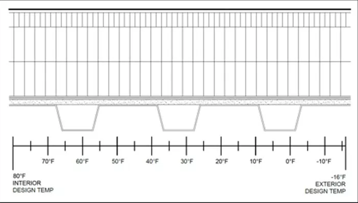
Step 3: Draw the roof assembly to a practical scale. A scale of 3 inches=1 foot works well and typically fits on a standard 8.5×11 size sheet. Underneath the roof assembly, draw a temperature scale below the roof assembly. The starting temperature, i.e., the left side of the scale, will be the winter interior dry bulb design temperature. The scale will end with the winter exterior design dry bulb temperature. Then, place evenly spaced vertical lines between these two lines to represent 5- and/or 10-degree increments. See below.
Step 4: Determine the roof assembly’s overall R-value. Thermal properties of roofing materials can be obtained from manufacturers’ product literature. Other possible sources include: Chapter 26—Thermal Transmission Data of the 2017 ASHRAE Handbook—Fundamentals; or the Appendix of The NRCA Roofing Manual: Architectural Metal Flashing and Condensation and Air Leakage Control—2018.
Below are the R-values for the proposed roof assembly.
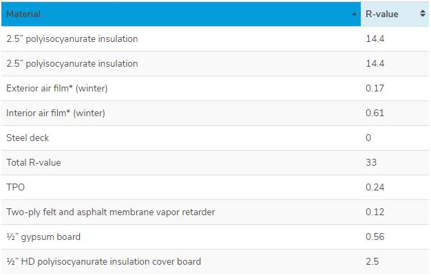
*Note that an “air film” exists on both the inside and outside of a roof assembly. Air films actually have an R-value and they contribute to a roof assembly’s overall R-value. Also, there are different R-values for interior and exterior air films for winter and summer.
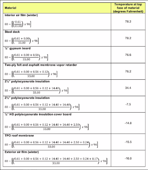
Step 5: Calculate the amount of heat loss occurring at the top surface of each material/layer. The temperature at the top of each material is lower as we move from interior to exterior. The heat loss formula for temperature drop (Td) is:
Td = Ti – [(R/RT) x ΔT]
where:
Td = temperature drop (temperature at top surface of material), degree Fahrenheit
Ti = design inside (interior side) temperature, degrees Fahrenheit
ΔT = (winter interior design dry bulb temperature) – (exterior design dry bulb temperature)
ΔT = 80 degrees – (-16 degrees) = 96 degrees
R = cumulative R-values of materials starting from the interior
RT = R-value of the total assembly
The table below are the calculations for each roofing material in the roof assembly example.
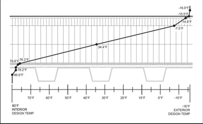
Step 6: Plot the calculated temperature gradient values for top surface of each material on the roof assembly drawing. Draw a line from the winter interior dry bulb design temperature to the next value and continue to “connect the dots” until you reach the winter exterior design dry bulb temperature.
Step 7: Determine the dew-point temperature. Dew-point temperature can be determined by using a simplified version of the ASHRAE psychrometric chart, shown below.
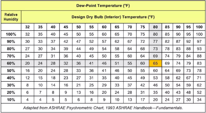
For this example, look at the top row of the chart and locate the design dry bulb (interior) temperature column, which, in this case, is 80°F. Next, locate 60 percent relative humidity on the left side of the chart. The dew-point temperature is at the intersection of the design dry bulb temperature column and relative humidity row. For this example, the dew point temperature is 65°F.
Note: If the design values don’t exactly match the values in the chart, you can use linear interpolation to determine the dew point temperature. Another option is to use a dew-point calculator app, such as www.dpcalc.org.
Step 8: Locate the dew-point temperature value on the temperature gradient line on the roof assembly drawing. If the dew-point temperature falls within the insulation that is above the vapor retarder, there is sufficient roof insulation above the vapor retarder. So the vapor retarder should be effective in preventing or minimizing condensation from occurring within the roof assembly.
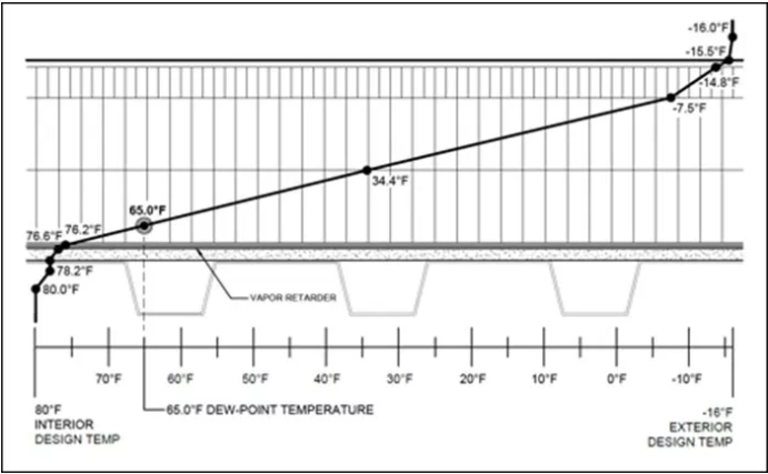
If the dew point falls below the vapor retarder, additional insulation is needed. After selecting a new amount of roof insulation, confirm the new amount is sufficient by doing the graphic analysis again. Conversely, if the dew-point temperature falls within the upper layer of insulation—say in the upper one-third of the total insulation layer—the amount of roof insulation might be able to be reduced to prevent condensation, as long as the dew point stays within the insulation and, importantly, the revised insulation amount still meets energy code requirements. Of course, perform another graphic analysis to verify the reduced insulation amount is adequate.
In closing
It is very important to note that this graphical method is a simplified procedure using theoretical constant values. In the real world, actual relative humidity and dew-point temperature values constantly change. This procedure is just one way to determine whether a vapor retarder will perform its intended function. Designers should further substantiate their analyses by using other methods.
NOTE: This blog is for information purposes only. GAF does not provide professional design services. You should always consult with a design professional to determine whether the roofing system to be installed is suitable for the particular needs of your building.
Learn more about GAF at www.gaf.com.
Source: GAF
Recommended For You

Marketing como un motor de crecimiento
Read More ...
When the danger is invisible
Read More ...
Championing mental health
Read More ...


Comments
Leave a Reply
Have an account? Login to leave a comment!
Sign In