


Parapets Part 1 — Continuity of Control Layers

By Benjamin Meyer, GAF.
The parapet is so much more than the intersection of roof and wall.
It’s also the junction where building aesthetics meets structural performance, air and moisture management, energy efficiency, construction trade sequencing, and operational maintenance. Each of these perspectives is critical for the long-term performance of the building, but they are often at odds with one another. At such a critical interface, proper parapet detailing, installation coordination, and execution are paramount. Continuity of water, air, thermal, and vapor control layers are necessary for long term performance.
Types of Parapets
Parapets can be assembled in many configurations and each requires project-specific detailing. The 2018 International Building Code (IBC) defines a parapet as “the part of any wall entirely above the roof line.” To simplify the discussion a bit, this article will look at a baseline flush edge condition and two primary parapet types — platform framed and balloon framed — defined by how the roof and wall structure are connected.
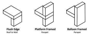
Parapets can generally be composed of structural materials such as wood framing, light gauge metal framing, pre-engineered steel, concrete, or masonry. The flush edge roof-to-wall connection is the simplest approach, with the roof structure placed above the wall system. Compared to the platform or balloon-framed parapets, the flush edge configuration provides the least wind uplift protection for the system at the roof edge, and the most limited aesthetic options.
Platform-framed parapets are similar to the flush edged construction, with the roof structure sitting directly on the wall system, but include a parapet wall assembly on top of the roof structure. In this configuration, the roof structure acts as a platform for the parapet wall above. Depending on the attachment method, height, and materials of the parapet wall, additional lateral and/or wind bracing strategies may be needed for this type of parapet.
Balloon Framed parapets are formed when the wall system bypasses the roof system to form a wall that extends above the roofline. In this configuration, the roof structure is commonly hung from the wall structure or supported by a separate superstructure inboard of the wall system.
Control Layer Continuity
To better understand common parapet challenges, it is important to review continuity across the roof and wall systems, specifically the key four Control Layers: Water, Air, Thermal, and Vapor.
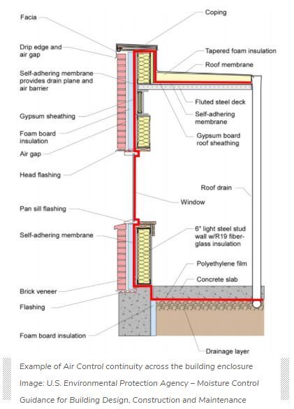
These four key Control Layers should generally be continuous across all six sides of the building enclosure. ASTM E2947 defines the term “building enclosure” to “refer collectively to materials, components, systems, and assemblies intended to provide shelter and environmental separation between interior and exterior, or between two or more environmentally distinct interior spaces in a building or structure.” It is difficult to achieve effective Control Layer continuity across the building systems, especially at significant transitions like a parapet, where the roof system meets the wall system. The “pen test” — tracing each of the control layers across the building enclosure — is a helpful tool to design and communicate to the field the intent of the critical components and functions of the building enclosure.
Water Control
Goal:
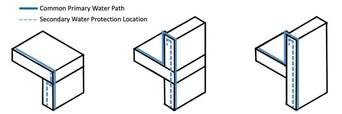
Keeping water out of buildings is a function of both roofs and walls, so it’s reasonable to assume parapets should do the same.
Principles:
Construction-related moisture, installation deficiencies, and damage in the use-phase can introduce moisture into the roof and wall systems. Construction acceptance testing, scheduled inspections, and regular maintenance play an important role in ensuring the systems are able to meet their intended performance over time.
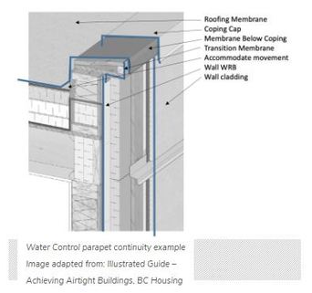
The figure above shows the individual components that we need to consider. In a parapet condition, it starts with managing the flow of water on the parapet coping cap back to the roof system to prevent staining on the exterior wall. Where the roof membrane meets the parapet wall, the membrane should be installed to allow for the possibility of differential movement, and terminated with flashing/counterflashing, under the coping cap or under an appropriate transition membrane. Wall systems commonly include a secondary water management layer behind the exterior cladding. For instance, it is important to protect the top of the wall assembly with a membrane below the parapet cap, treated at the coping cap clip fasteners, and lapping over the wall’s secondary water management layer in shingle fashion.
Air Control
Goal:
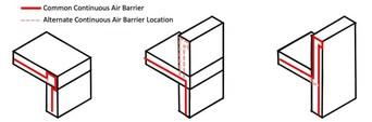
Most buildings require a continuous air barrier. If you think of a building as a solid 3D shape, like a cube, then the air barrier must be continuously detailed across all six sides of the building enclosure to be effective.
Principles:
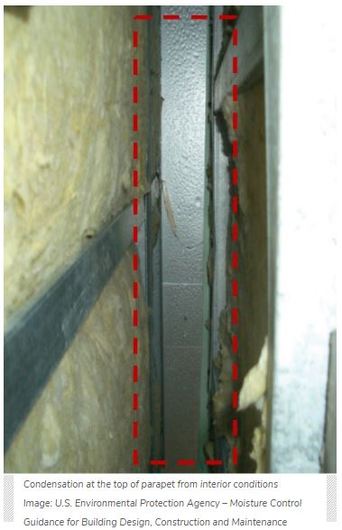
To achieve continuity, the air control layer requires much more than selecting a material or specifying a lab-rated assembly. Air control discontinuities in parapets can lead to water ingress, impact occupant comfort, waste energy from loss of conditioned air, cause damage from significant condensation moisture, and transmit airborne contaminants through the building enclosure. The amount of moisture transported through the building enclosure via an air leakage pathway at normal interior to exterior pressure differences is many times greater than the amount of water vapor that can pass through a permeable material due to vapor diffusion alone. When it comes to the air control layer, parapets are among the most challenging areas to get right.
Roof membranes are generally very good at blocking airflow, but unless they are designed to be part of the continuous air barrier system, and tied into the other five sides, the building will still leak air (more here about roof membranes).
For low-slope roof systems it can be beneficial to design the primary air control layer as the roof deck or to the topside of the roof deck. An example of this would be air sealing the penetrations to a concrete roof deck or installing a dedicated membrane to the roof deck, prior to installing insulation. Clearly identifying and communicating the air control layer in the roof system simplifies detailing at penetrations and transitioning at the parapet wall.
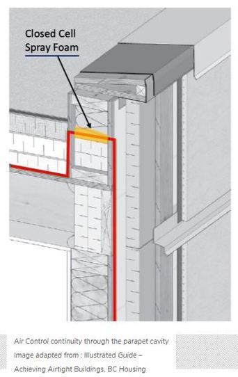
Installing an air barrier after the parapet wall is in place is difficult to get right. It requires significant coordination among trades to install the air control layer up and around the parapet wall, transition to the coping cap flashing, and terminate to the wall system air control on the other side of the wall. One alternative is to connect the air control layer from the roof side of the wall to the exterior wall by insulating within the wall cavity with a closed-cell spray foam. While this may be the “fussiest” option with regards to blocking, trade coordination, and use of specialty trades, in some cases, such as balloon framed light-gauge stud walls, it may be the best (or only) option.The case of a flush edge is fairly straightforward; maintain continuity of the air control layer either over or under the roof edge blocking and terminate over the wall air barrier system.
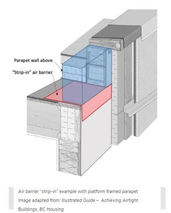
When the parapet wall is built on top of the roof deck, as in a platform framed parapet, it gets a bit trickier. The best option for continuity is to “strip-in” the air barrier to the roof deck before framing the parapet wall above the roof deck. Though the strip-in method is preferred as a way of keeping conditioned air out of the parapet, it requires significant trade coordination and is not often implemented in the field. To accomplish it successfully, the stripped-in portion of the air barrier should be installed with excess material on either side of the roof edge. Then frame the parapet wall on top of the roof deck, and connect the excess stripped-in membrane to the air control materials on the wall and at the roof deck.
Thermal Control
Goal:
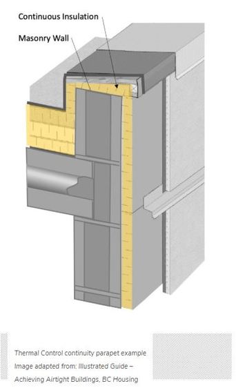
Maintaining continuity of the insulation layer, especially the continuous exterior insulation, across the parapet is important to achieve the intended energy performance and to prevent moisture condensation on cold surfaces.
Principles:
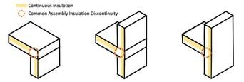
In current 2015 IECC and ASHRAE 90.1 national model commercial energy codes, the basic prescriptive requirements for both walls and roof systems include the use of continuous insulation in many climate zones and construction types. Continuous insulation is far more effective than cavity insulation, which is tucked into the voids between framing members. In parapets, the framing members are exposed to exterior conditions on both sides of the wall, rendering cavity insulation highly ineffective. Across the flush roof edge and parapets, maintaining continuity of the “continuous insulation” can be tricky. Even with continuous insulation designed in the roof and wall systems, a common thermal discontinuity emerges where the roof system meets the backside of the parapet wall. These discontinuities are important because they represent thermal bridges in the thermal control layer.
For the flush edge condition, the thermal discontinuity primarily results from the intersection of roof edge blocking for terminating the roof system and wall cladding at the transition. The compactness of this detail makes it difficult to simply add insulation. The roof edge blocking should be a wood-based material, which has a much lower thermal conductivity than steel. Roof framing members over the wall below should be covered by the continuous insulation from the wall system below. That is, don’t stop the continuous insulation short of roof framing edge conditions!
For platform-framed and balloon-framed parapets, tactics for maintaining the thermal control layer may be specific to the wall framing material that extends past the roof. For walls composed of concrete, insulated precast, mass masonry, or steel framing, the best approach may be to go up and over the wall with continuous insulation. In this case, continuous insulation is applied to the roof side of the parapet wall under the coping blocking at the top of the wall and connected to the continuous insulation on the exterior wall. If the parapet walls are tall cavity walls, this may not be ideal. Although insulated, the 2-sided exposure and limited conditioning of the air in the cavity space within the parapet could still lead to condensation moisture on cold surfaces.
Another strategy that is better-suited for wood-framed and very tall steel-framed walls is to effectively, but not literally, extend the roof thermal control layer through the backside of the parapet cavity wall and connect on the other side to the exterior wall continuous insulation. This is similar to the strategy described in the Air Control section, using closed-cell spray foam to connect the control layer from the roof side of the wall to the exterior wall within the wall cavity. As stated previously, this may still be the “fussiest” option. It is, however, well suited for wood-framed walls where thermal bridging is less pronounced than steel framing, and with tall steel-framed cavities where even continuously insulated, air-controlled parapets can result in condensation due to their exposure and isolation from the regular interior space conditioning. It is important to note that when insulating across the parapet wall cavity, air-permeable insulation like fiber batts is not effective. If interior air can bypass or travel through the insulation, it can still lead to condensation and moisture problems in the parapet above the air-permeable insulation.
Vapor Control
Goal:
The primary function of a dedicated vapor control layer is to prevent condensation that results from vapor diffusion. Vapor diffusion occurs when water molecules in the air (vapor) pass through a solid material due to a pressure differential (high to low) on either side of the material.
Principles:
Vapor diffusion through a solid material, even a vapor-permeable one, is a slow process. There are specific scenarios where enough vapor is able to diffuse through a solid material (not carried along by air leakage) to result in significant moisture accumulation over time. (Think of all the moisture that can potentially accumulate in a roof system as a concrete roof slab cures.) When it comes to vapor control, it is also possible to cause moisture problems by adding a vapor impermeable material to an assembly, intentionally or unintentionally. All materials — from insulation to membranes, air barriers, sheet metal, sheathing boards, paint, adhesives, and so on — have some level of vapor-retarding properties. Be sure to consult with a building enclosure professional to understand what materials may act as a vapor retarder in the roof, wall, and parapet assemblies.
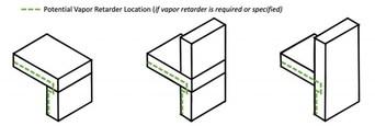
Not all wall, roof, and parapet scenarios require a vapor control layer. In fact, adding a vapor barrier to a design without consulting with a building enclosure professional can lead to unintended moisture problems, such as preventing an assembly from drying from incidental moisture. Many times when vapor control is discussed, the conversation quickly slips into “air control” strategies to manage condensation-related issues — as air movement can transport up to many times more moisture than vapor diffusion alone. Vapor retarding materials often also act as air barriers, and can be incorporated into the continuous air barrier design. As designing and installing continuous air barriers becomes required in most buildings, the confusion regarding air barriers and vapor retarders still exists (more about air barrier vs. vapor retarders here).
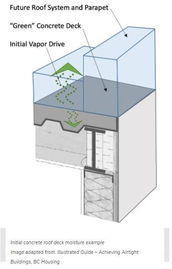
For parapets and roof systems in general, one of the more challenging vapor control scenarios involves newly poured or “green” concrete roof decks. Significant initial moisture within the concrete will diffuse into the rest of the system or interior (due to its high vapor pressure) over a potentially long time. If the concrete is placed on a steel composite deck and can’t dry downward through the steel, then moisture in the concrete will drive to the exterior (upward) through the roof system, wetting the roof system along the way. A common strategy is to install a Class I or better vapor retarder on the top surface of the concrete deck to prevent the moisture from rising. However, a self-adhered vapor retarding material will not always stick to high moisture concrete. If a vapor barrier is to be installed above the concrete deck, a vented steel composite deck may be helpful as a means to provide a path for downward drying of the concrete. Alternatively, an above-deck vapor retarder that allows horizontal movement of moisture with perimeter venting (think insulating lightweight concrete roof design) may also be beneficial.
Complexity is Common
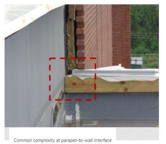
Parapet assemblies include numerous components and accessories. That often results in complicated interfaces even before reviewing design-specific conditions. Critical detail locations are often difficult to illustrate on 2D drawings alone, and can require exploded diagrams and/or sequence information to communicate the design intent. Additional complexity is common for parapets at the following locations:
- Parapet wall terminating into an adjacent building wall.
- Height or material changes of the parapet wall.
- Parapet with cladding on both sides of the wall system
- Roof eave and soffit conditions extending past the exterior wall face
- Curtain Walls extending beyond the roofline
- Inside/outside corners of parapet walls
- Scuppers and other penetrations
Engaging a building enclosure professional and selecting products with details and field support to assist in maintaining the four key control layers (water, air, thermal, and vapor) is critical to achieving optimal performance of the building enclosure.
Coordination is Key
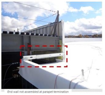
End wall not assembled at parapet termination
The project design and details should consider construction sequencing, access, and replacement across the expected life of the building. The framing contractor, for example, should be allowed to complete construction of the primary framing before beginning installation of the air barrier components. Sequencing the work of different trades makes it easier to coordinate air barrier installation. Sometimes it’s necessary for one trade to pause one phase of work in order to pre-treat a critical interface before proceeding (e.g. “pre-stripping” the roof joint at a platform framed parapet wall.) Early, clear, and frequent communication helps to keep everyone on the same page.The following are best practices for enabling communication between the owner, general contractor, trade contractor, architect, building enclosure professional, and performance testing agency:
Prior to Construction –
- Meet with design team, contractor, and affected sub-trades to discuss control layer continuity strategy and details
- Affirm the expected service life of the building and systems installed in conjunction with the control layers
- Make final material selections and confirm compatibility of substrates and accessories across roof and wall systems
- Confirm requirements for manufacturer warranties and/or guarantees across wall and roof systems
- Confirm sequencing and mobilization expectations across trades. Who goes first? Who has to come back?
- Discuss the quality control and quality assurance procedures during installation
- Prepare mock-up(s) demonstrating the parapet details
During Construction –
- Weather and overnight protection during onsite parapet assembly
- Consult product literature prior to use of all roof and wall products to ensure instructions are followed at parapets
- Install control layer pre-stripping, blocking and accessories, as required, at penetrations, details, and interfaces to maintain continuity
- Minimize “blind” attachment through exterior finishes into the structure and sheathing
- Involve manufacturer or certified professionals, as required, to establish warranty and/or guarantee requirements
- Notify enclosure professional when air barrier details are ready for review
- Perform qualitative and/or quantitative testing to verify water and air control performance and identify air leakage locations; document any resulting design changes
After Occupancy –
- Document and communicate critical continuity details for maintenance and replacement in the future
- This includes methods for maintaining air barrier continuity upon replacement when the roof membrane is designed as part of the continuous air barrier, and/or conditions where “hidden” elements like closed cell spray foam in the parapet assembly are integral to the performance of future replacements
- Perform, schedule, and document regular inspections, maintenance, and repairs of the parapet conditions
Learn more about GAF.
Original article source: GAF
Recommended For You

Supporting contractor success across the West
Read More ...
Todo es una cadena durante el proceso de instalación - Parte 1
Read More ...
Jobba Select Webinar: Insights Into Your Service Department Part 2 Featuring Ross Friedman
Read More ...

")


Comments
Leave a Reply
Have an account? Login to leave a comment!
Sign In